- Linkwell, Link our world Well!
- marketing01@mylinkwell.com

Single Mode vs Multimode Fiber, What is The Difference?
2023-05-15
PLC splitter types
2023-06-29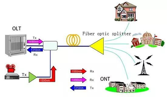
Understand what is fiber optic splitter
The fiber optic splitter, also known as the fiber optic coupler, is a device that is used to split a single optical signal into multiple signals. An important component in fiber optic communication systems allows a single optical fiber to be shared among multiple users or devices. This component is crucial for efficient communication.
Fiber Optic Splitter Working Principle
The phenomenon of light interference forms the working principle of a fiber optic splitter. Several fibers are fused together with a piece of optical fiber to form the splitter. The source of the optical signal is connected to the input fiber, and the receivers are connected to the output fibers.
When the input signal is applied to the splitter, it is split into multiple output signals. Controlling the interference between the light waves traveling through the different fibers achieves this. The design of the splitter causes the light waves to interfere constructively or destructively, depending on the relative phase of the waves.


Fiber Optic Splitter Types
There are several types of fiber optic splitters, including:
Fused Biconic Taper (FBT) Splitters: FBT splitters are made by fusing and tapering two or more fibers together. They are typically used in low-cost applications and are available in a variety of configurations, such as 1×2, 1×4, 1×8, and 1×16.
Planar Lightwave Circuit (PLC) Splitters: PLC splitters are made using a silica-based waveguide chip. This allows for a more precise split of the optical signal. They are more expensive than FBT splitters but offer better performance and are available in higher configurations, such as 1×32 and 1×64.

Differences between FBT splitter and PLC splitter
Fused Singlemode Fiber (FSMF) Splitters: FSMF splitters are similar to FBT splitters but are made using single-mode fiber, which allows for a higher split ratio and better performance.
Polarization-Maintaining (PM) Splitters: PM splitters are used in applications where the polarization of the optical signal needs to be maintained. They are typically used in fiber optic sensors and other high-precision applications.
How to Choose the Right Fiber Optic Splitter
Split Ratio
The split ratio is the ratio of the output power to the input power. When choosing a splitter, you need to consider the number of outputs you require and the split ratio of each output. For example, a 1:4 splitter will split the input signal into four equal outputs, while a 1:8 splitter will split the input signal into eight equal outputs.
Insertion Loss
Insertion loss is the amount of signal loss that occurs when the signal passes through the splitter. You should choose a splitter with low insertion loss to minimize signal attenuation. PLC splitters typically have lower insertion loss than FBT splitters.
Wavelength Compatibility
The splitter should be compatible with the wavelength of the input signal. Single-mode splitters are designed for use with single-mode fiber and have a narrow wavelength range, while multimode splitters are designed for use with multimode fiber and have a wider wavelength range.
Environmental Conditions
You should consider the environmental conditions in which the splitter will be used, such as temperature, humidity, and vibration. Some splitters are designed for use in harsh environments and are more rugged than others.
Conclusion
In summary, fiber optic splitter is an important device that plays a critical role in fiber optic communication systems. Its ability to split a single optical signal into multiple signals allows multiple users to share the same fiber optic cable, which can significantly reduce the cost and complexity of fiber optic networks.


